Inspiration
The first time I told someone I was building an amp for fun, they asked me, "Why would you do that? Can't you just buy one?" Well, I guess you can.
It would certainly cost a few times more than I spent to build it, but that's besides the point. Really, what got me started was the fact that over the years,
I've had a few amps. One was a 100W Yamaha, basically a piece of junk. Then I picked up a NAD C350, which was really pretty good, but more power than I needed.
A few years later, I sold that
and bought a Dynaco ST-35 . This little amp, which I paid $350 for and
dates back to the early 60's really sounded the best. I couldn't believe this almost 50 year old amp, which had probably less than 50 parts to it sounded so good.
Usually, if you look at a typical schematic from a modern amp that you would buy at Best Buy or something, there is like a million parts to it.
Looking at the schematic of the Dynaco(scroll to page 12),the input stage contains a typical
phase inverter stage. I wondered why I needed this stage. After all, if I had a CD player or other source with balanced outputs, couldn't I just drive the output
stage directly? Well, I needed a bit more gain than that, so I would need one input stage, but the phase inverter could be deleted. Whether this was a good idea or
not wasn't known to me yet, I just wanted to try it out. Also, although the ST-35 was still running strong, how long could it really go? 100 years? Who knows, maybe.
I could probably improve on it after some research, so lets build something new.
The Design
The design was built around some circuit boards (Simple SE) from a website called Tubelab.
These fantastic boards were designed to be run as single ended amplifiers. Using two of them, a push pull amp could be made. To use them like this,
they must be driven from a source with a balanced output.
Here is the original schematic from Tubelab
using the board as a single ended amp as designed.
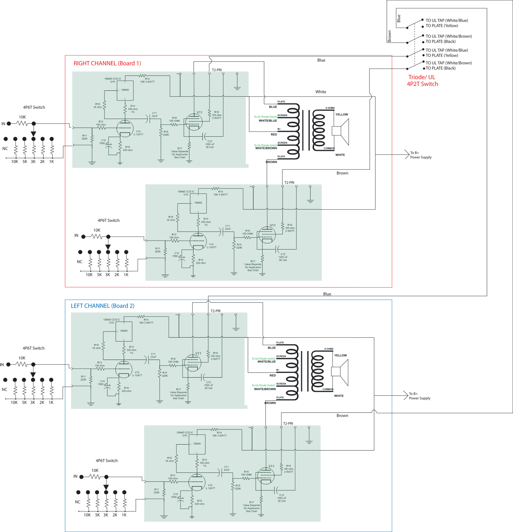
Here is my schematic with the necessary changes to make it push pull. (shown w/o power supply section)
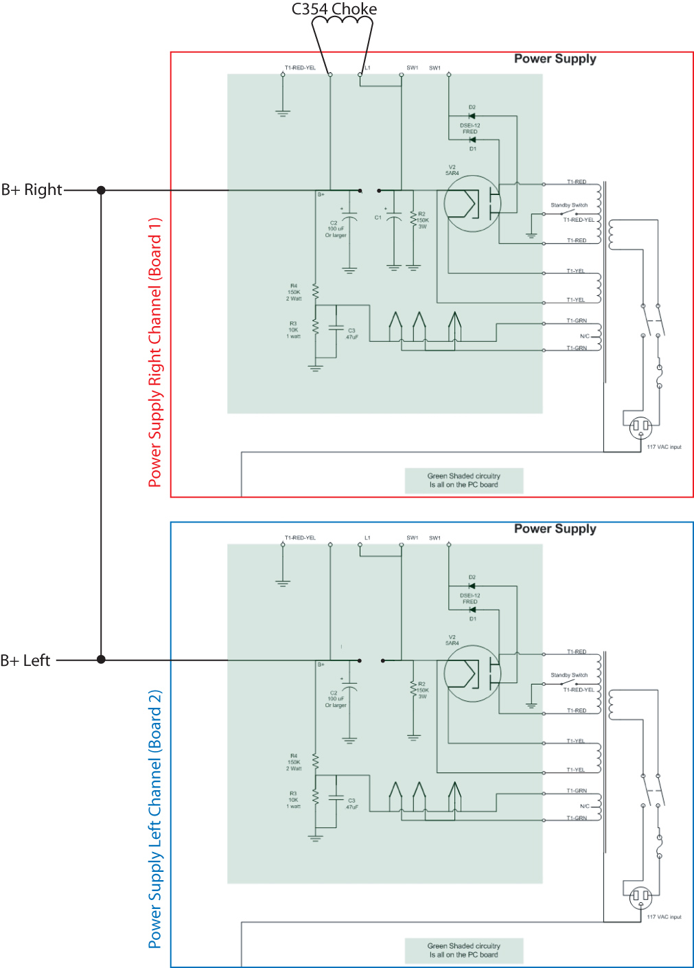
Here is the schematic for the power supply section. As you can see, I am running both channels off one rectifier tube.
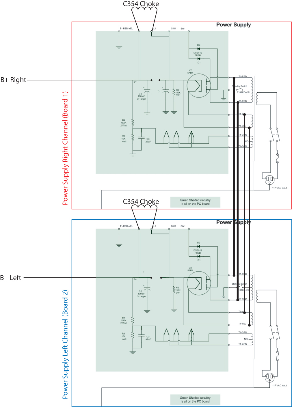
Alternatively, the power supplies can be run independently, using 2 rectifier tubes and 2 chokes, seen here. But I found that to be unnecessary since the 6v6's
are such a light load. The PA060 transformer I used has 2 filament windings, so it would not be necessary to jump those wires. I left the 2nd rectifier tube socket
available, and a few extra holes on the top of the chassis for another choke, just in case I ever wanted to go that route.
The Chassis and Assembly
Getting a nice enclosure was probably the hardest part. I ended up picking up one from diyhifisupply.com.
I drew up the hole patterns, and had a machinest cut it out for me. If the machinest can run the file on their CNC, it won't cost too much, but if it has
to be done by hand it will cost a fair amount. Here is the file.
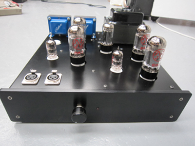
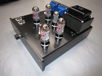
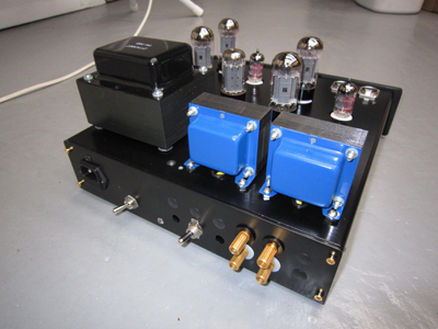
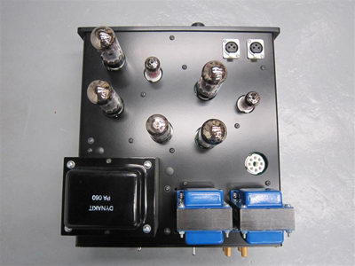
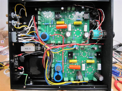
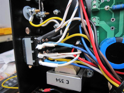
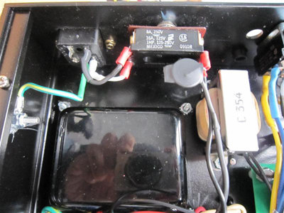
This enclosure was barely big enough. Here are a few looks under the hood.
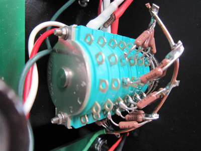
I ended up using 4 poles from a 6P6T switch wired up in shunt mode as the volume control. I am using a digital volume
control from a Sonos to control volume, so I only needed a coarse range selector here.
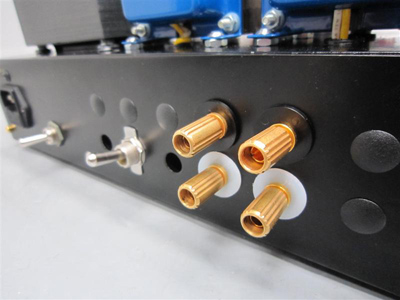
Got the switch at Surplus Sales of Nebraska. i got some cool gold WWII era
binding posts there too.
Tube Selection
I originally was going to build a KT88 or El34 PP amp. In fact, that's how I originally had it set up. But it was way too much power.
Measuring the outputs while I was listening, I was only using about 1W at normal listening
levels. When listening at ear blistering levels, I was using about 3W on transients or bass.
Dissapating more than 100W to listen at 3W makes almost no sense, not to mention that I have to attenuate a perfectly good 2V
signal to around 50mV just to get a reasonably not too loud result. Plus the transformer was getting HOT! Probably Ok, since its the
same transformer as an ST-70 (actually more laminations than the original), but still.
My advice would be really figure out how much power you
really need before you design an amp. My speakers are rated at 98db/1W/M, so I really didn't need very much power at all.
Well, no harm done. I ended up switching to a 6V6 type tube instead. I think these tubes sounded better anyway,
and I wasn't heating up my living room. The power supply settled around 420-430V, so
it is important NOT to use
NOS tubes in this amp. The new JJ6V6S as well as Electro Harmonix 6V6's can take 450-500V, so I am restricted to using these newer
tubes for this. I think there are some other manufacturers who are making new higher rated 6V6's. I think the old 6V6's want to see
around 300V or less.
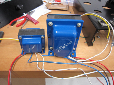
Going down from the EL34's to the 6V6S's also allowed me to shrink the size of the output transformers. Originally, I had the 25W Edcors (CXPP25-8-7.6K).
They sounded pretty good, but I thought the high end was down. I switched to their tiny 10W versions, at only $25 a piece. I was worried
that I would not get as much bass response with the smaller ones. THIS WAS NOT TRUE AT ALL. I had great bass with these as well a lot of
detail up high. These things are an incredible bargain. Here's a photo of the small which replaced the big.
Output Power
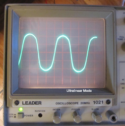
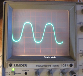
Using a resistive load, I measured about 11W Peak/6W RMS per channel in triode mode, and 15W Peak/8W RMS per channel in UL, before visible distortion.
The picks below show the scope w 5V per division into a 8 Ohm power resistor. I used 200Hz, for no particular reason, except that at 1K it hurts my ears when
testing with a speaker.
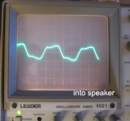
When testing throug a speaker, there was visible distortion starting around 3W. This is not a problem for me, since it results in over 100db in my room.
Also, the distortion shows up running a single frequency, but I doubt it would occur with musical material.
I am convinced that this is not a problem with the amp, but is rather due to back EMF and low damping factor. If I even tap on the cones of the speaker,
I will get a resultant voltage at the outputs of the amp. The speaker is acting like a mic, and generating voltage. At 3W, the speakers are moving a tremendous
amount within the magnet. Something with the resonances in the cabinet, or the physical movement of the cones is causing the distortion. I believe that if the
speaker sensitivity was less, say 93db or so, I would be able to get a good 8W with no noticeable distortion, since that would result in a similar
amount of cone movement, just at higher power. Interestingly, I measured a similar phenomenon at similar levels with a 17Wpc Dynaco ST-35.
My hunch is that to drive my speakers into the 110db range, requires not much voltage, but a very low output impedence from the amp, which tube amps are
generally not. There also is probably an impedance peak in the speakers at this frequency.
Comments
Overall, I am very pleased with the result. I think the amp sounds great, and is a few notches up from the old ST-35. Its just about the right amount of power for me, with plenty to spare. I don't have the right software to do a proper analysis, but that doesn't matter too much. Thanks everyone at diyaudio.com for their help and comments as I was building, and George at Tubelab for the great boards and suggestions along the way.
Parts List
This parts list is pretty much the same as the parts list on Tubelabs site for the single ended version, but just double all the quantities. Also, the list shows the transformers I used.